| Edit Values | |
| Skylake (server) µarch | |
| General Info | |
| Arch Type | CPU |
| Designer | Intel |
| Manufacturer | Intel |
| Introduction | May 4, 2017 |
| Process | 14 nm |
| Core Configs | 4, 6, 8, 10, 12, 14, 16, 18, 20, 22, 24, 26, 28 |
| Pipeline | |
| Type | Superscalar |
| OoOE | Yes |
| Speculative | Yes |
| Reg Renaming | Yes |
| Stages | 14-19 |
| Instructions | |
| ISA | x86-16, x86-32, x86-64 |
| Extensions | MOVBE, MMX, SSE, SSE2, SSE3, SSSE3, SSE4.1, SSE4.2, POPCNT, AVX, AVX2, AES, PCLMUL, FSGSBASE, RDRND, FMA3, F16C, BMI, BMI2, VT-x, VT-d, TXT, TSX, RDSEED, ADCX, PREFETCHW, CLFLUSHOPT, XSAVE, SGX, MPX, AVX-512 |
| Cache | |
| L1I Cache | 32 KiB/core 8-way set associative |
| L1D Cache | 32 KiB/core 8-way set associative |
| L2 Cache | 1 MiB/core 16-way set associative |
| L3 Cache | 1.375 MiB/core 11-way set associative |
| Cores | |
| Core Names | Skylake X, Skylake SP |
| Succession | |
There are a number of major differences in the Skylake server configuration vs the client configuration.
Contents
Pipeline
- See also: Client Architecture
All the changes and improvements done to the client pipeline is also found in the server configuration.
Front-end
Other than the large amount of changes described in client front-end, there are no server-specific changes that were done to the front-end with the exception of the LSD. The Loop Stream Detector (LSD) has been disabled. While the exact reason is not known, it might be related to a severe issue that was experienced by the OCaml Development Team. The issue was patched via microcode on the client platform, however this change might indicate it was possibly disabled on there as well. The exact implications of this are unknown.
Execution engine
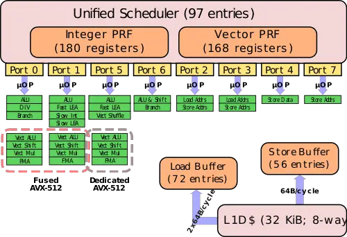
This is the first implementation to incorporate AVX-512, a 512-bit SIMD x86 instruction set extension. Intel introduced AVX-512 in two different ways:
In the simple implementation, the variants used in the entry-level and mid-range Xeon servers, AVX-512 fuses Port 0 and Port 1 to form a 512-bit unit. Since those two ports are 256-wide, an AVX-512 option that is dispatched by the scheduler to port 0 will execute on both ports. Note that unrelated operations can still execute in parallel. For example, an AVX-512 operation and an Int ALU operation may execute in parallel - the AVX-512 is dispatched on port 0 and use the AVX unit on port 1 as well and the Int ALU operation will execute independently in parallel on port 1.
In the high-end and highest performance Xeons, Intel added a second dedicated AVX-512 unit in addition to the fused Port0-1 operations described above. The dedicated unit is situated on Port 5.
Implementation
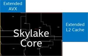
Physically, Intel added 768 KiB L2 cache and the second AVX-512 VPU externally to the core.
Memory subsystem
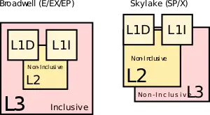
The medium level cache (MLC) and last level cache (LLC) was rebalanced. Traditionally, Intel had a 256 KiB L2 cache which was duplicated along with the L1s over in the LLC which was 2.5 MiB. That is, prior to Skylake, the 256 KiB L2 cache actually took up 512 KiB of space for a total of 2.25 mebibytes effective cache per core. In Skylake Intel doubled the L2 and quadrupled the effective capacity to 1 MiB while decreasing the LLC to 1.375 MiB. The LLC is also now made non-inclusive, i.e., the L2 may or may not be in the L3 (no guarantee is made); what stored where will depend on the particular access pattern of the executing application, the size of code and data accessed, and the inter-core sharing behavior. Having an inclusive L3 makes cache coherence considerably easier to implement. Snooping only requires checking the L3 cache tags to know if the data is on board and in which core. It also makes passing data around a bit more efficient. It's currently unknown what mechanism is being used to reduce snooping. In the past, Intel has discussed a couple of additional options they were researching such as NCID (non-inclusive cache, inclusive directory architecture). It's possible that a NCID is being used in Skylake or a related derivative. These changes also mean that software optimized for data placing in the various caches needs to be revised for the new changes, particularly in situations where data is not shared, the overall capacity can be treated as L2+L3 for a total of 2.375 MiB.
Mesh Architecture
On the previous number of generations, Intel has been adding cores onto the die and connecting them via a ring architecture. This was sufficient until recently. With each generation, the added cores increased the access latency while lowering the available bandwidth per core. Intel mitigated this problem by splitting up the die into two halves each on its own ring. This reduced hopping distance and added additional bandwidth but it did not solve the growing fundamental inefficiencies of the ring architecture.
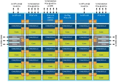
This was completely addressed with the new mesh architecture that is implemented in the Skylake server processors. The mesh is arranged as a matrix of vertical and horizontal communication paths which allow communication to take the shortest path to the correct node. The new mesh architecture implements a modular design for the routing resources in order to remove the various bottlenecks. That is, the mesh architecture now integrates the caching agent, the home agent, and the IO subsystem on the mesh interconnect distributed across all the cores. Each core now has its own associated LLC slice as well as the snooping filter and the Caching and Home Agent (CHA). Additional nodes such as the two memory controllers, the Ultra Path Interconnect (UPI) nodes and PCIe are not independent node on the mesh as well and they now behave identically to any other node/core in the network. This means that in addition to the performance increase expected from core-to-core and core-to-memory latency, there should be substantial increase in I/O performance. The CHA which is found on each of the LLC slices now maps addresses being accessed to the specific LLC bank, memory controller, or I/O subsystem. This provides the necessary information required for the routing to take place.
Cache Coherency
Given the new mesh architecture, new tradeoffs were involved. The new UPI inter-socket links are a valuable resource that could bottlenecked when flooded with unnecessary cross-socket snoop requests. There's also considerably higher memory bandwidth with Skylake which can impact performance. As a compromise, the previous four snoop modes (no-snoop, early snoop, home snoop, and directory) have been reduced to just directory-base coherency. This also alleviates the implementation complex (which is already complex enough in itself).
It should be pointed out that the directory-base coherency optimizations that were done in previous generations have been furthered improved with Skylake - particularly OSB, HitME cache, IO directory cache. Skylake maintained support for Opportunistic Snoop Broadcast (OSB) which allows the network to opportunistically make use of the UPI links when idle or lightly loaded thereby avoiding an expensive memory directory lookup. With the mesh network and distributed CHAs, HitME is now distributed and scales with the CHAs, enhancing the speeding up of cache-to-cache transfers (Those are your migratory cache lines that frequently get transferred between nodes). Specifically for I/O operations, the I/O directory cache (IODC), which was introduced with Haswell, improves stream throughput by eliminating directory reads for InvItoE from snoopy caching agent. Previously this was implemented as a 64-entry directory cache to complement the directory in memory. In Skylake, with a distributed CHA at each node, the IODC is implemented as an eight-entry directory cache per CHA.
Sub-NUMA Clustering
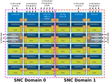
In previous generations Intel had a feature called cluster-on-die (COD) which was introduced with Haswell. With Skylake, there's a similar feature called sub-NUMA cluster (SNC). With a memory controller physically located on each side of the die, SNC allows for the creation of two localized domains with each memory controller belonging to each domain. The processor can then map the addresses from the controller to the distributed home ages and LLC in its domain. This allows executing code to experience lower LLC and memory latency within its domain compared to accesses outside of the domain.
It should be pointed out that in contrast to COD, SNC has a unique location for every adddress in the LCC and is evenr duplicated across LLC banks (previously, COD cache lines could have copies). Additionally, on multiprocessor system, address mapped to memory on remote sockets are still uniformally distributed across all LLC banks irrespective of the localized SNC domain.
Scalability
- See also: QuickPath Interconnect and Ultra Path Interconnect
In the last couple of generations, Intel has been utilizing QuickPath Interconnect (QPI) which served as a high-speed point-to-point interconnect. QPI has been replaced the Ultra Path Interconnect (UPI) which is higher-efficiency coherent interconnect for scalable systems, allowing multiple processors to share a single shared address space. Depending on the exact model, each processor can have either either two or three UPI links connecting to the other processors.
UPI links eliminate some of the scalability limited that surfaced in QPI. They use directory-based home snoop coherency protocol and operate at up either 10.4 GT/s or 9.6 GT/s. This is quite a bit different form previous generations. In addition to the various improvements done to the protocol layer, Skylake SP now implements a distributed CHA that is situated along with the LLC bank on each core. It's in charge of tracking the various requests form the core as well as responding to snoop requests from both local and remote agents. The ease of distributing the home agent is a result of Intel getting rid of the requirement on preallocation of resources at the home agent. This also means that future architectures should be able to scale up well.
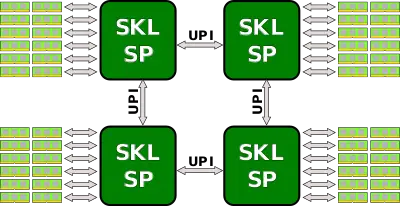
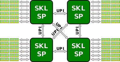
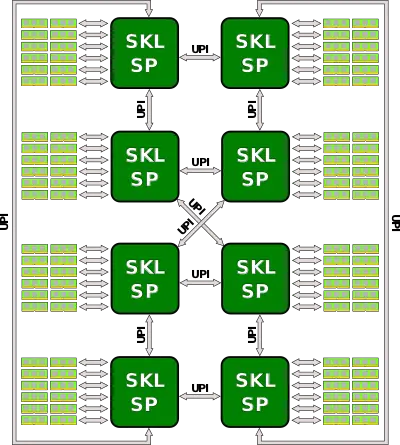
Depending on the exact model, Skylake processors can scale from 2-way all the way up to 8-way multiprocessing. Note that the high-end models that support 8-way multiprocessing also only come with three UPI links for this purpose while the lower end processors can have either two or three UPI links. Below are the typical configurations for those processors.
Integrated Omni-Path
- See also: Intel's Omni-Path
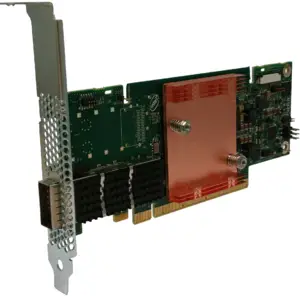
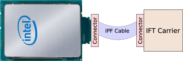
A number of Skylake SP models (specifically those with the "F" suffix) incorporate the Omni-Path Host Fabric Interface (HFI) on-package. This was previously done with the Knights Landing ("F" suffixed) models. This, in addition to improving cost and power efficiencies, also eliminates the dependency on the x16 PCIe lanes on the motherboard. With the HFI on package, the chip can be plugged in directly to the IFT (Internal Faceplate Transition) carrier via a separate IFP (Internal Faceplate-to-Processor) 1-port cable (effectively a Twinax cable).
See also
| codename | Skylake (server) + |
| core count | 4 +, 6 +, 8 +, 10 +, 12 +, 14 +, 16 +, 18 +, 20 +, 22 +, 24 +, 26 + and 28 + |
| designer | Intel + |
| first launched | May 4, 2017 + |
| full page name | intel/microarchitectures/skylake (server) + |
| instance of | microarchitecture + |
| instruction set architecture | x86-16 +, x86-32 + and x86-64 + |
| manufacturer | Intel + |
| microarchitecture type | CPU + |
| name | Skylake (server) + |
| pipeline stages (max) | 19 + |
| pipeline stages (min) | 14 + |
| process | 14 nm (0.014 μm, 1.4e-5 mm) + |
