| Edit Values | |
| Socket G34 | |
| General Info | |
| Designer | AMD |
| Introduction | March 29, 2010 (launched) |
| Market | Server |
| Microarchitecture | K10, Bulldozer, Piledriver |
| TDP | 140 W 140,000 mW 0.188 hp 0.14 kW |
| Package | |
| Name | LGA-1944 |
| Type | FC-OLGA |
| Contacts | 1944 |
| Dimension | 60.0 mm 6 cm × 42.5 mm2.362 in 4.25 cm 1.673 in |
| Pitch | 1.00 mm 0.0394 in |
| Socket | |
| Name | Socket G34 |
| Type | SM-LGA |
Socket G34 was designed for LGA-1944-packaged AMD Opteron 6000 Series microprocessors optimized for performance per Watt and scalability. The designation G34 stands for AMD's third generation server socket with four memory channels. Socket G34 has a DDR3 memory interface while its predecessors Socket 940 and Socket F were designed for DDR and DDR2 memory, respectively, and also offers additional HyperTransport links to improve the bandwidth and latency between nodes on multiprocessor systems. It has a smaller sibling Socket C32 which supports two memory channels and three HT links as the prior generations. Uniprocessor Opterons with a DDR3 interface were released in packages for Socket AM3 and AM3+ which make a single HT link available. Socket G34 was superseded by Socket SP3.
The LGA-1944 package is a multi-chip module integrating two dies, each providing four 16-bit HyperTransport Gen 3 links and two DDR3 memory controllers. Each HT link can be further unganged into two independent 8-bit links. The package has 1132 signal I/O, 341 power, and 471 ground pins. Package size constrained the HT interface to 64 lanes total, one x16 and one x8 link from node 0, two x16 links and one x8 link from node 1. One x16 link on node 0 is not connected, the remaining links connect the nodes in the package. Each link can be used for I/O, e.g. connecting a GPU through a HT-PCI bridge, or for cache coherent inter-socket traffic using an AMD proprietary protocol, with flexible routing permitting various network topologies on 2P and 4P systems. 8P systems were not considered due to insufficient demand.
Socket G34 was used in AMD's 2- and 4-socket "Maranello" reference platform. The processors for this socket are members of AMD's Family 10h with up to 12 CPU cores based on the K10 microarchitecture, and Family 15h featuring up to 8 compute units (not exactly 16 cores) based on the Bulldozer and Piledriver microarchitectures. They were fabricated on 45 nm and 32 nm processes.
Supposedly AMD originally planned a 1305-pin "Socket G3" for 1P to 8P systems with two DDR3 memory channels per socket. To reach higher memory capacities AMD proposed a "G3 Memory Extender" (G3MX) chip mounted on the motherboard to buffer the signals of four RDIMMs on two channels, and up to two G3MXs connected to each CPU memory channel.
Contents
Features[edit]
- Lidded land grid array package, 60.0 mm × 42.5 mm
- 4 × 64/72 bit DDR3 SDRAM interface up to 933 MHz, PC3-14900 (DDR3-1866), 29.87 GB/s total raw bandwidth
- 3 × 16 + 2 × 8 bit HyperTransport 1.0/3.0 interface up to 3200 MHz, 6400 MT/s, 12.8 GB/s in each direction
- HT Assist Technology (probe filter)
- Link Speed PowerCap (Fam. 15h)
- Link Width PowerCap (Fam. 15h)
- Managemement Features
- Advanced Platform Management Link (APML)
- SMBus v2.0-compatible interface
- Remote-Management Interface (SB-RMI)
- Power Management
- Multiple low-power states
- Independent Dynamic Core Technology (Fam. 10h)
- AMD CoolCore Technology (Fam. 10h)
- Dual Dynamic Power Management (Fam. 10h)
- Advanced Power Management (Fam. 15h)
- AMD Turbo CORE technology with per core power gating (Fam. 15h)
- CPU PowerCap (Fam. 15h)
- Effective frequency interface (Fam. 15h)
- ACPI-compliant
- Supported power states Fam. 10h: C0, C1, C1E, S0, S1, S3, S4, S5
- Supported power states Fam. 15h: C0, C1, C1E, C6, CC6, S0, S3, S4, S5
- Hardware thermal control
Chipsets[edit]
- AMD SR5690, SR5670, SR5650
- AMD SP5100 southbridge
Processors using Socket G34[edit]
- Opteron 6100 "Magny Cours"
- Opteron 6200 "Interlagos"
- Opteron 6300 "Abu Dhabi", "Warsaw"
- Embedded Opteron (same silicon as "Magny Cours")
| List of all Socket G34-based Processors | |||||||||||||||||||
|---|---|---|---|---|---|---|---|---|---|---|---|---|---|---|---|---|---|---|---|
| Model | Price | Process | Launched | µarch | Family | Core | C | T | Freq | Turbo | TDP | ||||||||
| Count: 0 | |||||||||||||||||||
Photos[edit]
Package Diagram[edit]
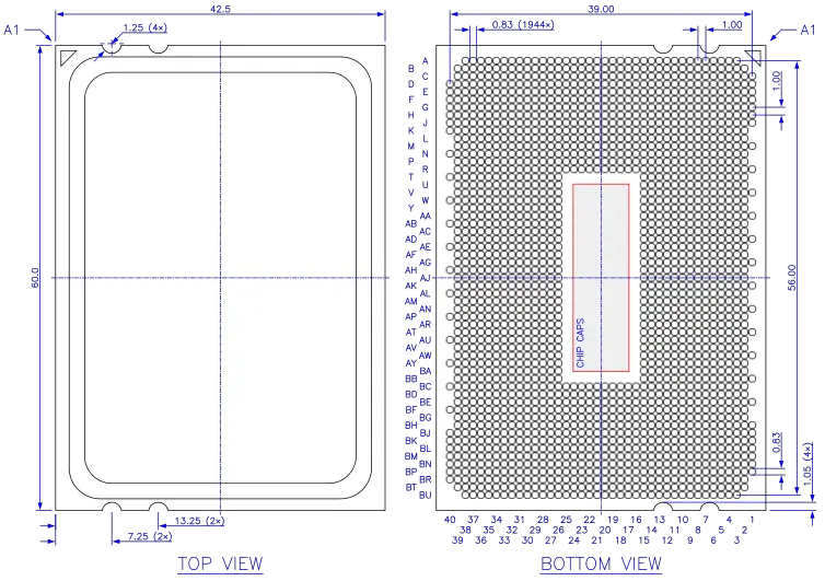
LGA-1944 package. All dimensions in millimeters.
Socket Diagram[edit]
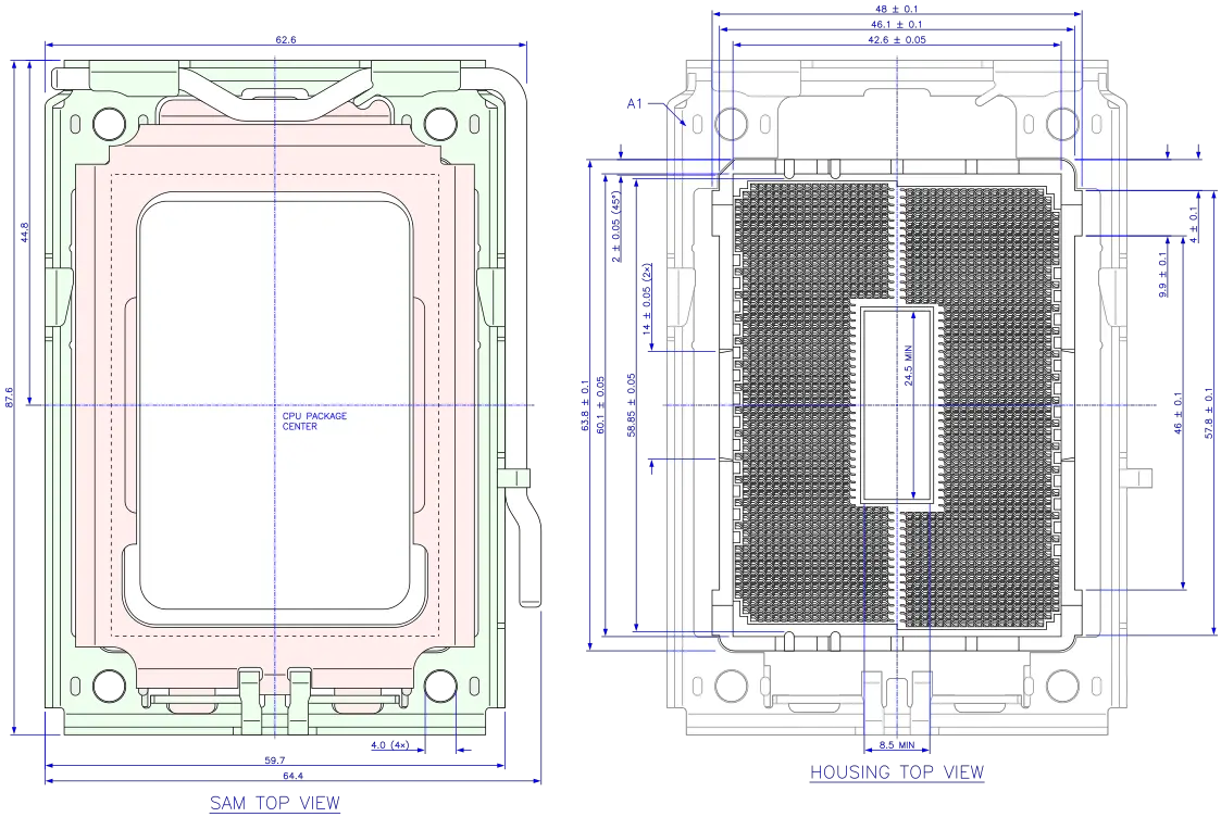
Dimensions of TE Connectivity LGA Socket 1944 (G34), Part No. 2069189. All dimensions in millimeters.
PCB layout of TE Connectivity Socket G34. All dimensions in millimeters.
Pin Map[edit]
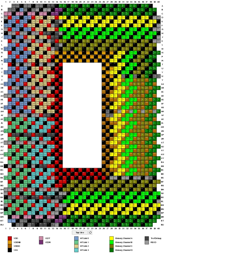
Socket G34 pinout, top view. This is a preview, click for a larger image and other views.
Pin Description[edit]
| Signal | Description |
|---|---|
| MA/MB/MC/MD_ADD[15:0] | DRAM Channel A-D Column/Row Address |
| MA/MB/MC/MD_BANK[2:0] | DRAM Bank Address |
| MA/MB/MC/MD_CAS_L | DRAM Column Address Strobe |
| MA/MB/MC/MD_CHECK[7:0] | DRAM ECC Bits |
| MA/MB/MC/MD_CKE[1:0] | DRAM Clock Enable |
| MA/MB/MC/MD_CLK_H/L[4:0] | DRAM Differential Clock |
| MA/MB/MC/MD_DATA[63:0] | DRAM Data Bus |
| MA/MB/MC/MD_DQS_H/L[17:0] | DRAM Differential Data Strobe |
| MA/MB/MC/MD_ERR_L | |
| MA/MB/MC/MD_EVENT_L | DRAM Thermal Event Status |
| MA/MB/MC/MD_PAR | |
| MA/MB/MC/MD_RAS_L | DRAM Row Address Strobe |
| MA/MB/MC/MD_RESET_L | DRAM Reset |
| MA/MB/MC/MD_WE_L | DRAM Write Enable |
| MA0/MA1_CS_L[1:0] MB0/MB1_CS_L[1:0] MC0/MC1_CS_L[1:0] MD0/MD1_CS_L[1:0] |
DRAM Chip Select |
| MA0/MA1/MA2/MA3_ODT[0] MB0/MB1/MB2/MB3_ODT[0] MC0/MC1/MC2/MC3_ODT[0] MD0/MD1/MD2/MD3_ODT[0] |
DRAM Enable Pin for On Die Termination |
| M_TEST | |
| M_VREF[1:0] | DRAM Interface Voltage Reference |
| M_ZVDDIO[1:0] | |
| L0/L1/L2/L3_CADIN_H/L[15:0] | HT Link 0-3 Differential Command/Address/Data Input |
| L0/L1/L2/L3_CADOUT_H/L[15:0] | HT Link 0-3 Differential Command/Address/Data Output |
| L0/L1/L2/L3_CLKIN_H/L[1:0] | HT Link 0-3 Differential Clock Input |
| L0/L1/L2/L3_CLKOUT_H/L[1:0] | HT Link 0-3 Differential Clock Output |
| L0/L1/L2/L3_CTLIN_H/L[1:0] | HT Link 0-3 Differential Control Input |
| L0/L1/L2/L3_CTLOUT_H/L[1:0] | HT Link 0-3 Differential Control Output |
| LDTSTOP_L | HT Stop Control Input for power management and link width and frequency change |
| HTREF0, | ? HT Compensation Resistor to VSS, VLDT |
| CLKIN_H/L | Differential PLL Reference Clock |
| PWROK | Voltages and CLKIN have reached specified operation |
| RESET_L | Processor Reset |
| ALERT_L | |
| PROCHOT_L | Processor in HTC-active state |
| SIC | Sideband Interface Clock[1] |
| SID | Sideband Interface Data |
| THERMTRIP_L | Temperature Trip |
| DBRDY | |
| DBREQ_L | Debug Request input to JTAG controller |
| TCK | JTAG Clock |
| TDI | JTAG Data Input |
| TDO | JTAG Data Output |
| TMS | JTAG Mode Select |
| TRST_L | JTAG Reset |
| TEST* | Test Pins |
| SVC | Serial VID Interface Clock |
| SVD | Serial VID Interface Data |
| VDD | Core power supply |
| VDD_SENSE | VDD voltage monitor pin |
| VDDA | |
| VDDIO | DRAM I/O ring power supply |
| VDDIO_FB_H/L | Differential feedback to VDDIO regulator |
| VDDNB | Northbridge power supply |
| VDDNB_SENSE | VDDNB voltage monitor pin |
| VDDR | VDDR power supply |
| VDDR_SENSE | VDDR voltage monitor pin |
| VLDT | HyperTransport I/O ring power supply |
| VLDT_SENSE | VLDT voltage monitor pin |
| VSS | Ground |
| VSS_SENSE | VSS sense output for voltage regulators |
| SA[2:0] | Socket Identifier |
| CPU_PRESENT_L | CPU Presence Indicator |
| RSVD | Reserved |
- ↑ The Sideband Interface (SBI) a.k.a. APML is a SMBus interconnect to the processor's SB-RMI and SB-TSI interfaces.
Bibliography[edit]
- "Family 10h AMD Opteron Processor Product Data Sheet", AMD Publ. #40036, Rev. 3.04, June 22, 2010
- "Family 15h Models 00h-0Fh AMD Opteron Processor Product Data Sheet", AMD Publ. #49687, Rev. 3.01, October 10, 2012
- "BIOS and Kernel Developer’s Guide (BKDG) For AMD Family 10h Processors", AMD Publ. #31116, Rev. 3.62, January 14, 2013
- "BIOS and Kernel Developer’s Guide (BKDG) for AMD Family 15h Models 00h-0Fh Processors", AMD Publ. #42301, Rev. 3.14, January 28, 2013
- "Revision Guide for AMD Family 10h Processors", AMD Publ. #41322, Rev. 3.92, March 2012
- "Revision Guide for AMD Family 15h Models 00h-0Fh Processors", AMD Publ. #48063, Rev. 3.24, September 30, 2014
- Conway, Pat et al. (2010). Cache Hierarchy and Memory Subsystem of the AMD Opteron Processor. IEEE Micro. 30 (2): 16-29. doi:10.1109/MM.2010.31
- Financial Analyst Day Presentation, November 11, 2009
See also[edit]
| designer | AMD + |
| first launched | March 29, 2010 + |
| instance of | package + |
| market segment | Server + |
| microarchitecture | K10 +, Bulldozer + and Piledriver + |
| name | Socket G34 + |
| package | LGA-1944 + |
| package contacts | 1,944 + |
| package length | 60 mm (6 cm, 2.362 in) + |
| package pitch | 1 mm (0.0394 in) + |
| package type | FC-OLGA + |
| package width | 42.5 mm (4.25 cm, 1.673 in) + |
| socket | Socket G34 + |
| tdp | 140 W (140,000 mW, 0.188 hp, 0.14 kW) + |


