| Edit Values | |
| Rosetta µarch | |
| General Info | |
| Arch Type | Switch |
| Designer | Cray |
| Manufacturer | TSMC |
| Introduction | 2019 |
| Process | 16 nm |
Rosetta is the microarchitecture for Cray's Slingshot ASIC Switch.
Contents
Process technology
Rosetta is implemented on TSMC 16 nm process
Release date
- First silicon September 2018
- Production November 2019
Rosetta is going into production with A0 silicon.
Overview
Rosetta is a custom ASIC switch that implements Cray's Slingshot interconnect. Implemented on 16 nm and consuming around 250 W, Rosetta is a 64-port switch. Each port is 200 Gbps/dir implemented as a standard 4-lane PAM4 56G.
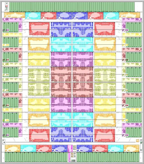
Rosetta uses a tiled architecture. There are 32 tiles in the center of the die and 32 additional tiles at the parameter. Each tile carries the functionality of two ports. The 32 tiles at the parameter of the die contain the peripheral functions containing the edge functionalities including the SerDes, Ethernet lookup functions, MAC/PCS/LLR, and others. In the center of the die are the 32 blocks with the remaining functionality.
Routing
Rosetta utilizes a tiled architecture organized as four rows of eight tiles. There are two switch ports per tile, therefore with 32 tiles, there are 64 ports. Rosetta is implemented as a hierarchical crossbar with distributed crossbars based on row busses, column channels, and per tile crossbar.
In other words, every port has its own row bus which communicates across its row. There is a set of eight-column channels that are connected to the eight ports within that column. Since there are two switch ports per tile, there are two of those eight-column channel sets. Per tile, there is a 16-input 8-output crossbar which does the corner turns to the four rows (with two ports per row tile, you need eight outputs in total).
For example, to go from Port18 to Port9, pockets are first routed from Port18 along the row-bus to the local crossbar on the 5th column. From the local crossbar, the pocket is then routed upward to Port9 along the column channels.
Crossbar
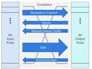
Within each tile is the 16:8 crossbar. Internally, the crossbar comprises 5 independent crossbars - requests to transmit, grants, request queue credits, data, and end-to-end acknowledgment. The chip relies on a virtual output queued architecture meaning the data comes to the input buffers and remains there until it's ready to be sent out. This allows for head-of-line (HOL) blocking
- Requests to transmit (Input->Output) - Prior to receiving the data, the header handled with the request to route the data is performed and arbitration request is initiated prior and while the data is still arriving.
- Grants (Output->Input) - A grant is sent back when a pocket has been granted to go; output buffer space is also reserved at that point
- Request queue credits (Output->Input) - A credit is sent back in order to make sure there is always enough space for the request to arrive at the output buffer
- Data (Input->Output)
- End-to-end Ack (Output->Input) - Used to keep track of data flow for congression control
Die
- TSMC 16 nm process
- 64 port
- 250 W
- tiled architecture
- 32 tile blocks
- peripheral function blocks
floorplan:
See also
Bibliography
- Cray, 2019 IEEE Symposium on High-Performance Interconnects (HOTI).
| codename | Rosetta + |
| designer | Cray + |
| first launched | 2019 + |
| full page name | cray/microarchitectures/rosetta + |
| instance of | microarchitecture + |
| manufacturer | TSMC + |
| name | Rosetta + |
| process | 16 nm (0.016 μm, 1.6e-5 mm) + |

