-
WikiChip
WikiChip
-
Architectures
Popular x86
-
Intel
- Client
- Server
- Big Cores
- Small Cores
-
AMD
Popular ARM
-
ARM
- Server
- Big
- Little
-
Cavium
-
Samsung
-
-
Chips
Popular Families
-
Ampere
-
Apple
-
Cavium
-
HiSilicon
-
MediaTek
-
NXP
-
Qualcomm
-
Renesas
-
Samsung
-
From WikiChip
Difference between revisions of "pulse-width modulation"
| Line 3: | Line 3: | ||
<math> | <math> | ||
\text{duty_cycle} = t_{on}f(t) = \frac{t_{on}}{t_{on}+t_{off}} | \text{duty_cycle} = t_{on}f(t) = \frac{t_{on}}{t_{on}+t_{off}} | ||
| − | </math> Where the duty_cycle can be controlled by varying ''t<sub>on</sub>'' or ''t<sub>off</sub>''. | + | </math> |
| + | Where the duty_cycle can be controlled by varying ''t<sub>on</sub>'' or ''t<sub>off</sub>''. | ||
Revision as of 11:26, 11 December 2013
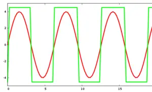
Pulse-width modulation (PWM), also known as pulse-duration modulation (PDM) is a technique of modulating the duration of the HIGH and LOW pulses of a digital signal. A PWM signal is a way of representing an analog signal in a digital circuit. The application of pulse-width modulation varies greatly from communication and encoding to controlling the power delivered to an external device such as a motor or an LED. The purpose of pulse-width modulation is to vary the duty cycle according to Where the duty_cycle can be controlled by varying ton or toff.
