(configuration & operation) |
|||
| (One intermediate revision by the same user not shown) | |||
| Line 82: | Line 82: | ||
The '''accelerator cache interface''' ('''ACI''') is a [[cascaded crossbar]] that connects the RAFs to the cache banks. This includes the transfer of both address and data. | The '''accelerator cache interface''' ('''ACI''') is a [[cascaded crossbar]] that connects the RAFs to the cache banks. This includes the transfer of both address and data. | ||
| − | === Configuration === | + | === Configuration & Extraction === |
| − | The CSA fabric includes support for runtime services | + | The CSA fabric includes support for runtime services. Runtime services are overlayed on hardware resources through a hierarchy of layers with each layer corresponding to a particular CSA network. A single controller interfaces with outside the tile in order to send and receive service commands as well as coordinate the regional controllers at the RAFs using the ACI. Regional controllers, in turn, coordinate local controllers at certain mezzanine network stops. At the lowest level, service-specific packet-based micro-protocols execute over the local network during a mode controlled through the mezzanine controllers. These micro-protocols allow each class of PEs to interact with the runtime service. This layered hierarchy topology allows adjacent networks on the same layer (e.g., all lowest level layers) to operate simultaneously. The parallel nature of the fabric allows configuring a tile in between a few 100s nanoseconds to a few microseconds, depending on the configuration size and its residency in the memory hierarchy. Only the logical (as opposed to temporal) state of the runtime service dataflow graph is preserved. |
==== Operation ==== | ==== Operation ==== | ||
| − | Configuration targets are organized into configuration chains. A controller drives an out-of-band signal to all fabric targets in its neighborhood. When this occurs, all PEs are paused and go into an unconfigured state. PEs | + | Configuration targets are organized into configuration chains. A controller drives an out-of-band signal to all fabric targets in its neighborhood. When this occurs, all PEs are paused and go into an unconfigured state. PEs receive their configuration packet, set it in their micro-protocol registers, and notify the subsequent PE in the chain that it may configure using the next packet. This process continues for all the targets in the chain. There is no size limit on the configuration packet and may also be variable length. For example, PEs configured with [[constant]] [[operands]] can have a longer packet size which incorporates the operands as [[immediate values]]. Unconfigured PEs maintain backpressure on the network while configured PEs can start executing right away without any sort of a centralized control. |
| + | |||
| + | Extraction is done in a similar fashion. Data and state bits are extracted from one target at a time. Extraction can be done non-destructively where the original state and dataflow graph may be configured back at a later time. This is done by funneling ever target state to an egress register to be scanned out through the local network. The CSA permits a light-overhead checkpoint through the use of a pipelined extraction of a narrow region of the fabric, allowing the rest of the fabric to continue to execute. | ||
== Bibliography == | == Bibliography == | ||
* Kermin E.F. et al. (July 5, 2018). US Patent No. US20180189231A1. | * Kermin E.F. et al. (July 5, 2018). US Patent No. US20180189231A1. | ||
Latest revision as of 19:19, 2 October 2018
Configurable Spatial Accelerator (CSA) is an explicit data graph execution architecture designed by Intel for the high-performance computing and data center markets. The CSA is designed to work alongside a traditional x86 core and serve as an acceleration engine.
Contents
Motivation[edit]
The push to exascale computing demands a very high floating-point performance while maintaining a very aggressive power budget. Intel claims that the CSA architecture is capable of replacing the traditional out-of-order superscalar while surpassing it in performance and power. CSA supports the same HPC programming models supported by traditional microprocessors.
Overview[edit]
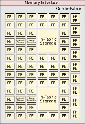
CSA claims to offer an order-of-magnitude gain in energy efficiency and performance relative to existing HPC microprocessors through the use of highly-dense and efficient atomic compute units. The basic structure of the configurable spatial accelerator (CSA) is a dense heterogeneous array of processing elements (PEs) tiles along with an on-die interconnect network and a memory interface. The array of processing elements can include integer arithmetic PEs, floating-point arithmetic PEs, communication circuitry, and in-fabric storage. This group of tiles may be stand-alone or may be part of an even larger tile. The accelerator executes data flow graphs directly instead traditional sequential instruction streams. Unlike an FPGA, the CSA supports full languages such as C++ and executes full programs. There is a one-to-one correspondence between the nodes in the compiler-generated graph and the CSA dataflow operator processing elements.
Each of the processing elements supports a few highly efficient operations, thus they can only handle a few of the dataflow graph operations. Different PEs support different operations of the dataflow graph. PEs execute simultaneously irrespective of the operations of the other PEs. PEs can execute a dataflow operation whenever it has input data available and there is sufficient space available for storing the output data. PE can execute immediately as soon as they are configured by the fabric.
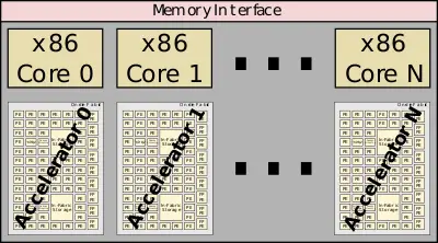
The configurable spatial accelerators are designed alongside a traditional x86 core. This allows the cores maintain legacy support and handle additional tasks that might be easier on a traditional core.
Architecture[edit]
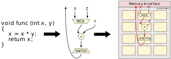
The CSA executes dataflow graphs directly. Those tend to look very similar to the compiler's own internal representation (IR) of compiled programs. The graph consists of operators and edges which are the transfer of data between operators. Dataflow tokens representing data values are injected into the dataflow graph for executions. Tokens flow between nodes to form a complete computation.
Suppose func is executed with 1 for X and 2 for Y. The value for X (a 1) may be a constant or a result of some other operation. A pick operation selects that correct input value and provides it to the downstream destination processing element. In this case, the pick outputs a data value of 1 to the multiplier to be multiplied by the value of Y (a 2). The multiplier outputs the value of 2 to the switch node which completes the operation and passes the value onward. Many such operations may be executed concurrently.
Communications arcs[edit]
Communications arcs are latency insensitive, asynchronous, point-to-point communications channels. Can be back-pressured by a processing element. When this happens data cannot pass (either producing or sending output). This may occur because the PE is simply unconfigured or there is no storage space available.
Memory[edit]
Memory operations are treated just like any other processing element as basic dataflow operators such as a load and a store. There are also some more complex operations such as in-memory atomics and consistency operators with similar semantics to their von Neumann counterparts. For example, a load takes an address channel and populates a response channel with the output.
In the case of memory aliasing, since the CSA has no notion of a program counter, there are dependency tokens which allow compilers to define the order of memory accesses. A dependency token behaves like any other token but prevents memory operations from executing until a dependency token is received.
Runtime services[edit]
CSA provides a number of architectural facilities for dealing with things such as context switches, exceptions, and errors.
- Configuration - dataflow graph is loaded into the CSA
- Extraction - dataflow graph execution state is saved to memory
- Exceptions - handling mechanism for math, soft, and other errors
Configuration loads the dataflow graph and state from memory into the interconnect and processing elements. This also includes any dataflow tokens live in that graph that may have been in operation prior a context switch. PEs can start executing right away as soon as they are configured by the fabric. Any unconfigured PE simply backpressures their channel until they are configured. The CSA can be partitioned into privileged and user-level state. This can allow a primary configuration of the fabric to run without invoking the operating system.
Extraction saves the dataflow graph execution state to memory. Extractions are caused by similar events to exceptions such as illegal operator argument or RAS events. Exceptions may occur at the dataflow-operator level. On such exceptions, the operator halts and emits an exception message containing the operation identifier and details of the nature of the problem. The exception message can then be communicated to an associated core for service.
Microarchitecture[edit]
The spatial accelerator itself consists of a heterogeneous mix of small, highly energy-efficient data-flow processing elements along with an interconnect and support for flow control in order to support real-world applications. Targeting different workloads, certain processing elements can be made to target specific applications such as custom double-precision fused multiply-add PEs for HPC and low-precision floating point PEs for deep neural networks acceleration.
Processing elements[edit]
Programs are converted to dataflow graphs that are mapped onto the architecture by configuring PEs and the network to express the control dataflow graph of the program. For the most part, the processing elements comprise dataflow operators. Those operators correspond to a micro-instruction or a set of micro-instructions. Some PEs are as simple as an integer operation or more complex such as a floating point FMA unit. PEs can also be architectural interfaces such as instruction pointer, triggered instruction, or be a state machine based architectural interface. PEs can execute right away once all input operands are available. The result of the PE is forwarded to downstream operators. Control, scheduling, and data storage are distributed among the PEs. Generally, data is streamed in from memory or cache through the fabric and back out to memory.
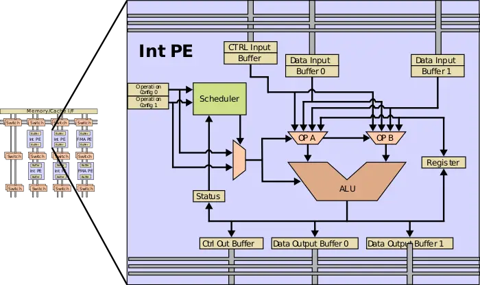
A simple integer PE is shown below which includes a number of I/O buffers, the ALU, a storage register, instruction registers, and a scheduler. Each cycle the scheduler can select an instruction for execution based on the availability of the input and output buffers and status of the PE. The result is saved to the output register which is sent to a downstream PE. The use of very simple registers instead of large banks and controls makes the PE very energy-efficient. Using the configured microcode, the scheduler examines the status of the PE ingress and egress buffers, and when all the inputs for the configured operations have arrived and the engress buffers of the operation is available, the ALU operation can execute with the result value being placed in the egress buffer.
The instruction registers are set during the configuration stage. Special auxiliary control wires and state are used to stream in configuration across the PEs on the fabric. Reconfiguration is very fast. A tile sized fabric can be configured in less than ~10μs.
Configurable network[edit]
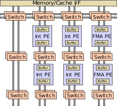
The configurable network comprises a series of multiplexers configured through various control signals. Those may be connected to processing elements and other networks and are used to steer data and valid bits from the producer to the consumer on the fabric. The width of a network can vary. In some networks on the fabric, the network is can be bufferless, allowing data to flow from producer to consumer in a single cycle while in other networks. Some networks can span a large part of the accelerator while other networks may be short local PE to PE interconnects. Multicast channels are also supported where a single input is sent to multiple consumers. During operation, a PE that is not ready can exert backpressure on the network. In addition to forwarding flow, logical conjunction can allow backflow which can handle returning control data from the consumer back to the producer using.
Some networks can be configured statically. At that stage, configuration bits (e.g. MUX selection and flow control function) are set at each network component. In the example above, four bits are needed per hop - one bit for the east/west MUXes and two bits for the north/south MUXes. Seven additional bits are required for the flow control function.
Memory subsystem[edit]
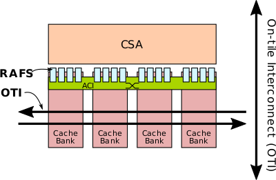
Since a dataflow graph is capable of generating a large number of parallel requests in word-granularity, in order to fulfill the bandwidth requirement, the memory subsystem uses multiple cache banks. Banks store full cache lines with each line residing in only one home in the cache. Cache lines are pseudo-randomly mapped to cache banks. For each cache bank, there are multiple RAFs.
Virtual addresses are translated to physical addresses using a channel-associative TLB. Serving as an intermediary between the CSA fabric and the memory hierarchy on the chip is the request address file (RAF) circuit. A single RAF circuit is multiplexed among several co-located memory operations in order to reduce area overhead and increase efficiency using a multi-port RAF. To provide sufficient bandwidth, multiple RAF circuits are attached to a single CSA tile. The RAF is tasked with the responsibility of interfacing the out-of-order memory subsystem with the in-order semantics of the CSA fabric as well as providing support for address translation and a page walker. A series of completion queues are used to re-order memory responses and return them to the fabric in request order. The RAF circuits operate similarly to other PEs by checking for input availability and output buffering, if needed, and can execute the memory operation as needed.
The accelerator cache interface (ACI) is a cascaded crossbar that connects the RAFs to the cache banks. This includes the transfer of both address and data.
Configuration & Extraction[edit]
The CSA fabric includes support for runtime services. Runtime services are overlayed on hardware resources through a hierarchy of layers with each layer corresponding to a particular CSA network. A single controller interfaces with outside the tile in order to send and receive service commands as well as coordinate the regional controllers at the RAFs using the ACI. Regional controllers, in turn, coordinate local controllers at certain mezzanine network stops. At the lowest level, service-specific packet-based micro-protocols execute over the local network during a mode controlled through the mezzanine controllers. These micro-protocols allow each class of PEs to interact with the runtime service. This layered hierarchy topology allows adjacent networks on the same layer (e.g., all lowest level layers) to operate simultaneously. The parallel nature of the fabric allows configuring a tile in between a few 100s nanoseconds to a few microseconds, depending on the configuration size and its residency in the memory hierarchy. Only the logical (as opposed to temporal) state of the runtime service dataflow graph is preserved.
Operation[edit]
Configuration targets are organized into configuration chains. A controller drives an out-of-band signal to all fabric targets in its neighborhood. When this occurs, all PEs are paused and go into an unconfigured state. PEs receive their configuration packet, set it in their micro-protocol registers, and notify the subsequent PE in the chain that it may configure using the next packet. This process continues for all the targets in the chain. There is no size limit on the configuration packet and may also be variable length. For example, PEs configured with constant operands can have a longer packet size which incorporates the operands as immediate values. Unconfigured PEs maintain backpressure on the network while configured PEs can start executing right away without any sort of a centralized control.
Extraction is done in a similar fashion. Data and state bits are extracted from one target at a time. Extraction can be done non-destructively where the original state and dataflow graph may be configured back at a later time. This is done by funneling ever target state to an egress register to be scanned out through the local network. The CSA permits a light-overhead checkpoint through the use of a pipelined extraction of a narrow region of the fabric, allowing the rest of the fabric to continue to execute.
Bibliography[edit]
- Kermin E.F. et al. (July 5, 2018). US Patent No. US20180189231A1.
