An Inverter or less commonly, a NOT gate, is a logic gate which implements logical negation. When the input is LOW, the output is HIGH and when the input is HIGH, the output is LOW. Inverters are the nucleus of all digital systems. Understanding its operation, behavior, and properties for a specific processor makes it possible to expand its design onto more complex structures such as NOR and NAND gates. The electrical behavior of much bigger and complex circuitry can be derived by extrapolating the behavior observed from simple inverters.
Functionality
| NOT Gate | |
|---|---|
| A | Q |
| 0 | 1 |
| 1 | 0 |
An inverter generates a signal that is logically opposite to its input. When the input is sufficiently LOW, the output generate is HIGH. Likewise, when the input is sufficiently HIGH, the output generate becomes LOW.
Expression:
Q = A = ¬A
Implementation
An inverter can be implemented using various transistor technologies.
CMOS Inverter
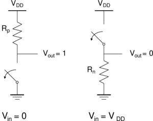
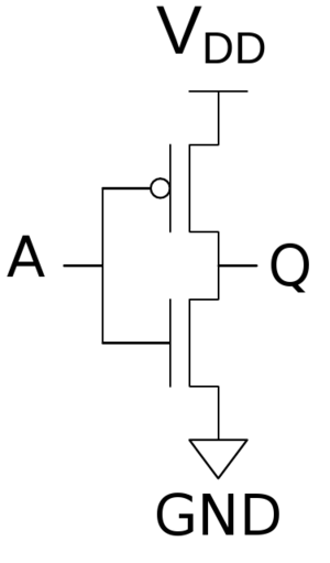
A static CMOS inverted can be constructed from a single nMOS transistor and a single pMOS transistor. As usual, the pMOS is connected to VDD and nMOS is connected to ground. When the input is LOW, the nMOS transistor is off and the pMOS transistor is on. The output is pulled up to HIGH as it's connected to VDD but not GND. When the input is HIGH, the nMOS transistor is on and the pMOS transistor is off yielding an output that is connected to GND.
| Steady State Response | |
|---|---|
 |
VOL = 0 VOH = VDD VM = f(Rn>, Rp) |
The Vth point of a CMOS inverter can be approximated using the following expression:
