A multiplexer (mux) is a digital device that selects one of its inputs and connects it to its output. A set of inputs called select lines determine which input should be passed to the output. A multiplexer is unidirectional - the flow is only from input to output.
Multiplexers are useful in any application in which data must be chosen from multiple sources to a single destination. Multiplexers are also heavily used in I/O operations, data buses, and register files.
A multiplexer with 2N input lines requires N select lines.
A typical example of a multiplexer is shown on the right. When Sel is 0, Q = I1. When Sel is 1, Q = I2.
Contents
[hide]Enable
It's often desirable to add an enable input EN to a multiplexer. An enable input makes the multiplexer operate. When EN = 0, the output is 0. When EN = 1, the multiplexer performs its operation depending on the selection line.
Variations
Many different variations of multiplexers exist.
2:1 Mux
A 2:1 Mux is the simplest multiplexer that can be made. Its selection lines are made of a single bit. A truth table is provided on the right. The logic function of a 2:1 Mux is: Q=(A ∧ S) ∨ (B ∧ S)

|
| ||||||||||||||||||||||||
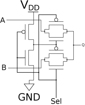
Very fast, CMOS-based, 2:1 Mux devices can be built using two transmission gates as shown below. Note that the implementation below is a nonrestoring multiplexer.
4:1 Mux
| Sel<0> | Sel<1> | I<0> | I<1> | I<2> | I<3> | Q |
|---|---|---|---|---|---|---|
| 0 | 0 | 0 | X | X | X | 0 |
| 0 | 0 | 1 | X | X | X | 1 |
| 0 | 1 | X | 0 | X | X | 0 |
| 0 | 1 | X | 1 | X | X | 1 |
| 1 | 0 | X | X | 0 | X | 0 |
| 1 | 0 | X | X | 1 | X | 1 |
| 1 | 1 | X | X | X | 1 | 1 |
| 1 | 1 | X | X | X | 0 | 0 |
A 4:1 Multiplexer is a common multiplexer that takes selects one input among 4 and connects it to its output based on a 2-bit select line. There are many way to construct a 4:1 Mux, one possibility is using 2:1 Mux as shown below:
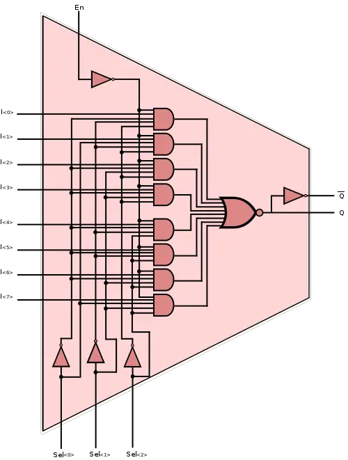
Alternatively, a 4:1 Mux can be built out of basic gates. Its function is shown below:
Q =
Where A, B, C, and D are the four inputs. Q is the output.
Larger Multiplexers
Multiplexers generally only come in a few common sizes. Even in ASIC design, arbitrary sized multiplexers are not always offered. Large multiplexers can always be built from a collection of smaller ones. Consider a register file with 32 registers where we only want to select a single register at any given time. Such multiplexer can be design from four 8:1 Mux.
74151 - 8:1 Mux
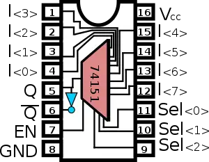
A common multiplexer is the 8:1 Mux which selects one of 8 bits of input. The 74151 is a popular 16-pin DIP IC that implements an 8:1 mux. Note that the implementation below is an active-low.
To the right is the typical schematic of the 74151, 16-pin DIP IC. Vcc is on pin 16 and GND is on pin 8. Pins 5 and 6 are the outputs, the output on pin 6 is the inverted version of the output on pin 5. The enable is on pin 7.
| 8:1 Mux | |||||
|---|---|---|---|---|---|
| Inputs | Output | ||||
| Select | Enable | ||||
| Sel<0> | Sel<1> | Sel<2> | EN | Q | Q |
| X | X | X | 1 | 1 | 0 |
| 0 | 0 | 0 | 0 | I<0> | I<0> |
| 0 | 0 | 1 | 0 | I<1> | I<1> |
| 0 | 1 | 0 | 0 | I<2> | I<2> |
| 0 | 1 | 1 | 0 | I<3> | I<3> |
| 1 | 0 | 0 | 0 | I<4> | I<4> |
| 1 | 0 | 1 | 0 | I<5> | I<5> |
| 1 | 1 | 0 | 0 | I<6> | I<6> |
| 1 | 1 | 1 | 0 | I<7> | I<7> |
Tri-State Outputs
Some commercial multiplexers have tri-state outputs. When the EN input is LOW, instead of the output being forced into 0, it gets forced into a Hi-Z state.


