From WikiChip
Difference between revisions of "majority gate"
| Line 6: | Line 6: | ||
|truth table = {{truth table/maj}} | |truth table = {{truth table/maj}} | ||
}} | }} | ||
| − | The '''majority gate''' ('''MAJ gate''') is a [[logic gate]] that implements the [[majority function]] - a device that outputs a [[HIGH]] when the majority of its inputs are HIGH, otherwise it outputs a | + | The '''majority gate''' ('''MAJ gate''') is a [[logic gate]] that implements the [[majority function]] - a device that outputs a [[HIGH]] when the majority of its inputs are HIGH, otherwise it outputs a [[LOW]]. |
| + | |||
| + | == MAJ3 == | ||
| + | <span style="display:inline-block;float: right; margin: 5px;">[[File:MAJ3 gate.svg|250px]]</span> | ||
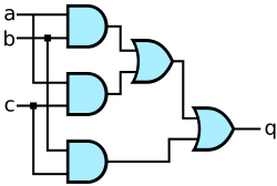
| + | A 3-input MAJ gate (MAJ3) can be implemented as <math>(a \land b) \lor (a \land c) \lor (b \land c)</math>. However the naive implementation will result in up to 30 transistors. Since <math>\text{MAJ}(a, b, c) = \overline{\overline{\text{MAJ}(a, b, c)}}</math>, we can define <math>\text{MAJ}(a, b, c) = \overline{\overline{(a \land b) \lor (a \land c) \lor (b \land c)}}</math> and that can be implemented using a single [[AOI|AOI222]] which is defined as <math>\text{AOI222}(a, b, c, d, e, f) = \overline{(a \land b) \lor (c \land d) \lor (e \land f)}</math> - i.e. <math>\text{MAJ}(a, b, c) = \overline{AOI222(a, b, c, a, b, c)}</math>. | ||
Revision as of 05:35, 25 November 2015
| MAJ Gate | ||||||||||||||||||||||||||||||||||||||||||||
| Typical Symbol | ||||||||||||||||||||||||||||||||||||||||||||
| Functional | ||||||||||||||||||||||||||||||||||||||||||||
| Truth Table | ||||||||||||||||||||||||||||||||||||||||||||
| ||||||||||||||||||||||||||||||||||||||||||||
| ||||||||||||||||||||||||||||||||||||||||||||
| ||||||||||||||||||||||||||||||||||||||||||||
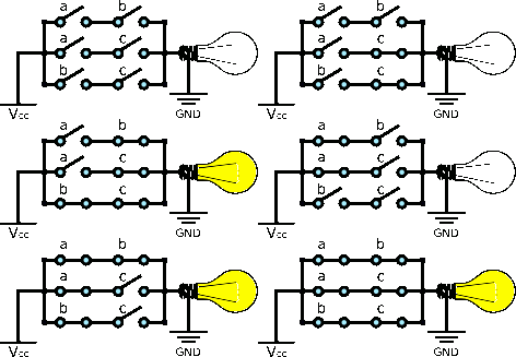
The majority gate (MAJ gate) is a logic gate that implements the majority function - a device that outputs a HIGH when the majority of its inputs are HIGH, otherwise it outputs a LOW.
MAJ3
 A 3-input MAJ gate (MAJ3) can be implemented as . However the naive implementation will result in up to 30 transistors. Since , we can define and that can be implemented using a single AOI222 which is defined as - i.e. .

